7.7 ILS Approach
ILS BASICS
NDB and VOR approaches, with their lateral guidance to the runway, greatly improve the reliability of flight schedules. But without the capability to provide vertical guidance to the runway they are limited in utility. No vertical guidance therefore classes them as non-precision approaches.
The Instrument Landing System adds glide-slope, or elevation information. Commonly called the ILS, it is the mother of them all when it comes to getting down close to the ground. This is a precision approach system and with modern equipment it can guide you right down to the runway—zero Decision-Height (DH) and zero visibility.
THE ILS COMPONENTS
When you fly the ILS, you’re following the co-location of two signals: a localiser for lateral guidance (VHF); and a glide slope for vertical guidance (UHF). When you tune your NAV receiver to a localiser frequency, a second receiver, the glide-slope receiver, is automatically tuned to its proper frequency. The pairing is automatic.
There’s more to an ILS than the localiser and glide slope signals.
The components are categorized as follows:
1. Guidance information: the localiser and glide slope.
2. Range information: the outer marker (OM) and the middle marker (MM) beacons or DME.
3. Visual information: approach lights, touchdown and centerline lights, runway lights.
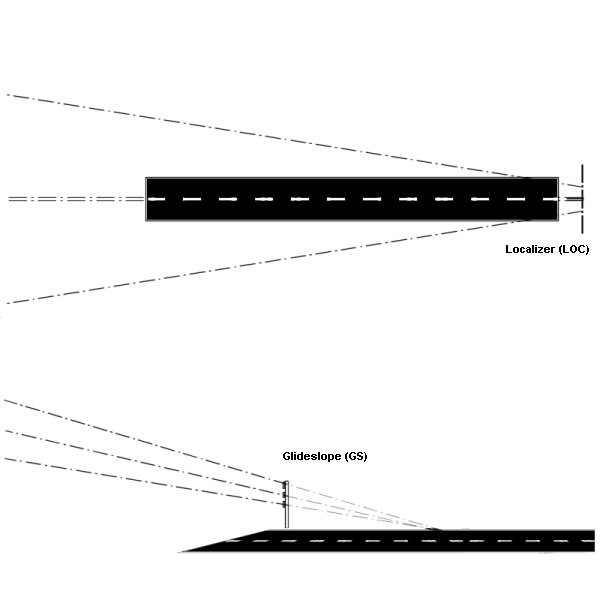

This is a three-dimensional depiction of the Instrument Landing System.
Early VOR indicators had the yellow and blue-colored arc as shown here, but it was later phased out because it provided no useful information. Localizer antennas shown at far end of runway.
DESCRIPTION OF THE LOCALISER AND GLIDESLOPE
THE LOCALISER
The localiser signal provides azimuth, or lateral information to guide the aircraft to the centerline of the runway. It is similar to a VOR signal except that it provides radial information for only a single course; which is the runway heading. Localiser information is displayed on the same indicator as your VOR information.
When tracking the localiser, the Pilot turns towards the needle in the same manner as with VOR navigation.
The localiser indicator reacts differently from a VOR in several ways:
- The localiser consists of only a single course.
- The localiser course needle is more sensitive than a VOR needle. For a VOR, a dot under the needle represents 2° deviation from course, while for the localiser, each dot under the needle represents 0.5° deviation from course.
- Because the localiser provides information for only one radial (runway heading), the NAV receiver automatically cuts out the OBS (Omni Bearing Selector knob). Rotating the OBS still rotates the course ring on the instrument, but has no effect on the needle. (It is recommended that you rotate the OBS so that the runway heading is at the top of the Nav. 1 reciever or DI/HSI in any case)
How sensitive is the Localiser? Near the Outer Marker, a one-dot deviation puts you about 500 ft. from the centerline. Near the Middle Marker, one dot means you’re off course by 150 ft.
Specifics of the Localizer:
- The localiser antenna is located at the far end of the runway.
- The approach course of the localiser is called the front course.
- The course line in the opposite direction to the front course is called the back course.
- The localiser signal is normally usable up to 18 NM from the field.
- The Morse code Identification of the localiser consists of a three-letter identifier preceeded by the letter “I”.
The Glideslope:
The Glideslope is the signal that provides vertical guidance to the aircraft during the ILS approach. The standard glideslope path is 3° downhill to the end of the runway. Follow it faithfully and your altitude will be precisely correct when you reach the touchdown zone of the runway.
Tracking the glideslope is identical to tracking a localiser. If the glideslope needle swings away from center, either up or down, maneuver the aircraft towards the needle by adjusting the engines power. Don’t pitch the aircrafts nose up or down.
REMEMBER: Pitch controls speed; Power controls rate of descent!

The glide path projection angle is normally adjusted to 3 degrees above the horizontal so that it intersects the MM at about 200 feet and the OM at about 1,400 feet above the runway elevation. The glide slope is normally usable to a distance of 10 NM.
Graphics courtesy of http://www.planesimulation.com